Wednesday 30 May 2018

Critical Review Assignment 3:


Assignment 3 Critical Review: 

1:1 Fuel Tank (Assignment 2):


- Approach:


Our approach towards the design of the 1:1 fuel tank, was heavily influenced by peanut bike tanks that have knee pads or indentations. Looking at these realize the potential of this feature produces a more interesting design and a more sporty look when featured on bike. The indentations flowed evenly with the dip  of the tank making an overall ascetically appealing design. From here we looked into various fuel tank design that consisted of this feature and understood the methods of fabrication and construction of these particular tanks, from initial templates to all the way to the welding and smoothing process. From this we brought forward the idea of having a torus like feature on the top surface of the fuel tank, making a more complex but appealing design.


From this particular approach we understood the Grasshopper script provided by Andrew Wallace, and discovered that the surfaces and shape were based of isocurves that could be tweaked parametrically and also manually. This was one major strength our team had in customizing the initial design with the parametric tool Grasshopper 3d.

Working with parametric software Grasshopper 3D

This how we produced and designed a final form for the laser cut template.


Attempting this design and approach multiple times incorporated various steps, processes and ideas on how to replicate the form. I was chosen to produce the left side panel for the 1:1 fuel tank.

Final form on template

- Strengths and Weaknesses:


With previous knowledge on digital fabrication in particular laser cutting and also knowledge on using the parametric tool of Grasshopper 3d were great strengths that our team members had. A major weakness was that none of us had worked with shaping metal sheets before in particular aluminium shaping. 
This was a good way of determining the cross over between digital fabrication methods with traditional fabrication methods. 


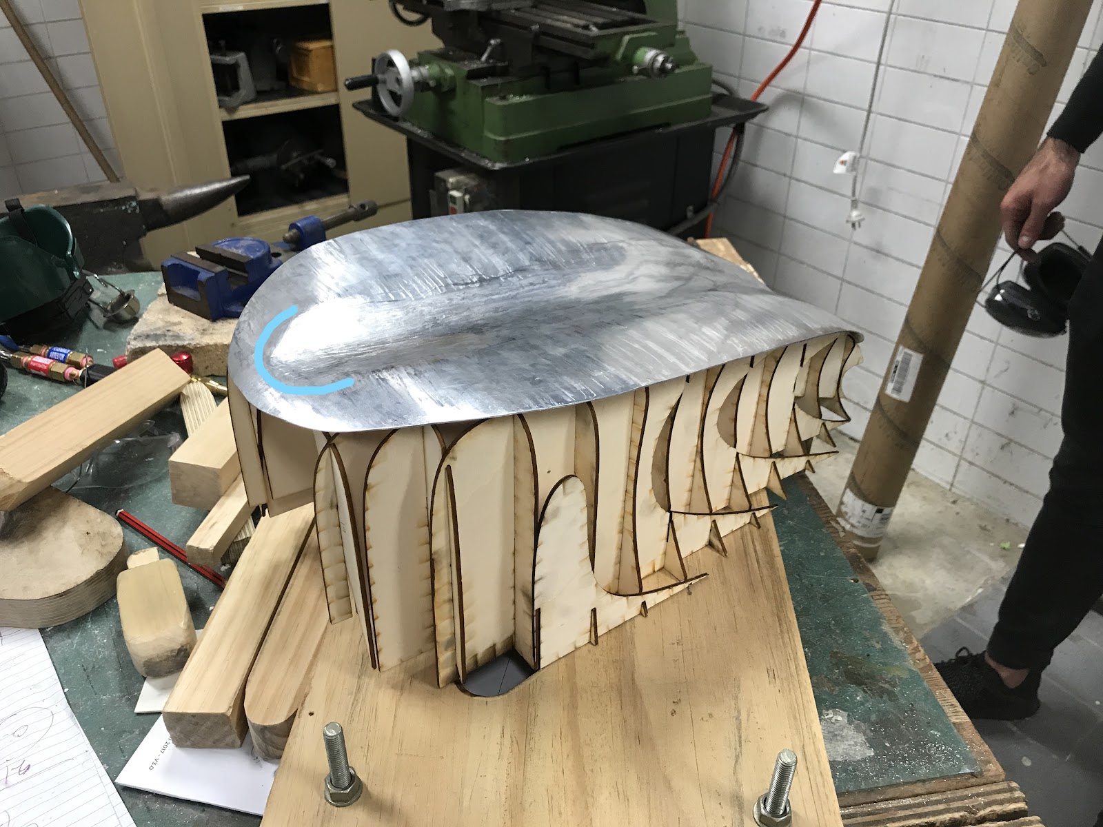
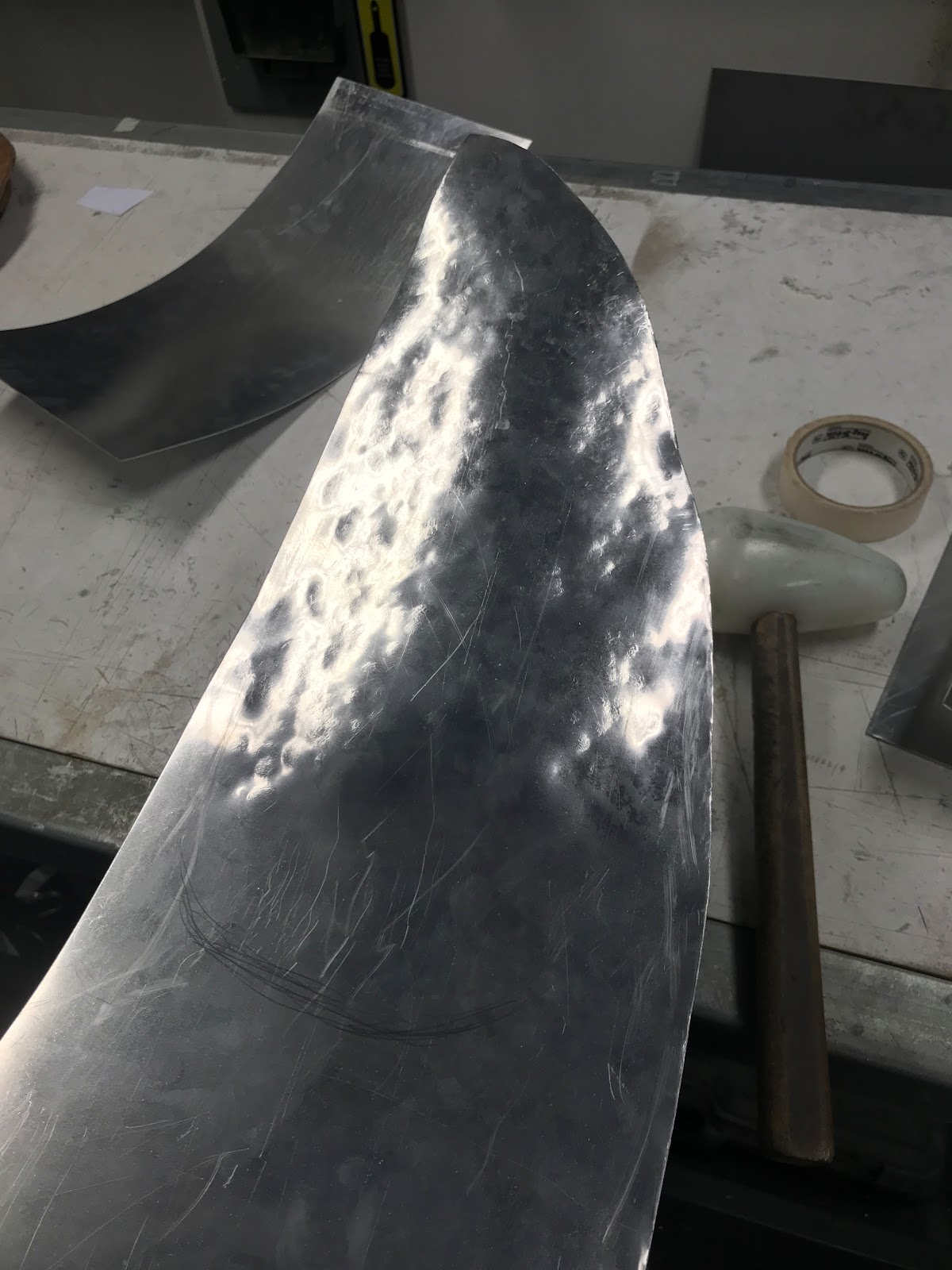
Directional curvature needed

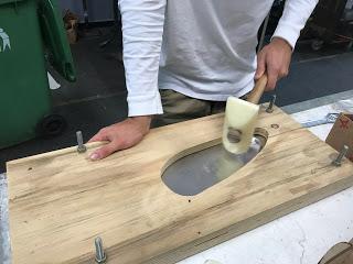
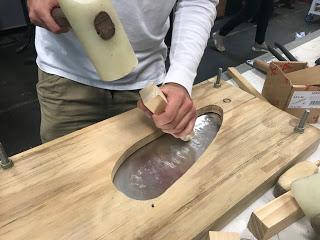
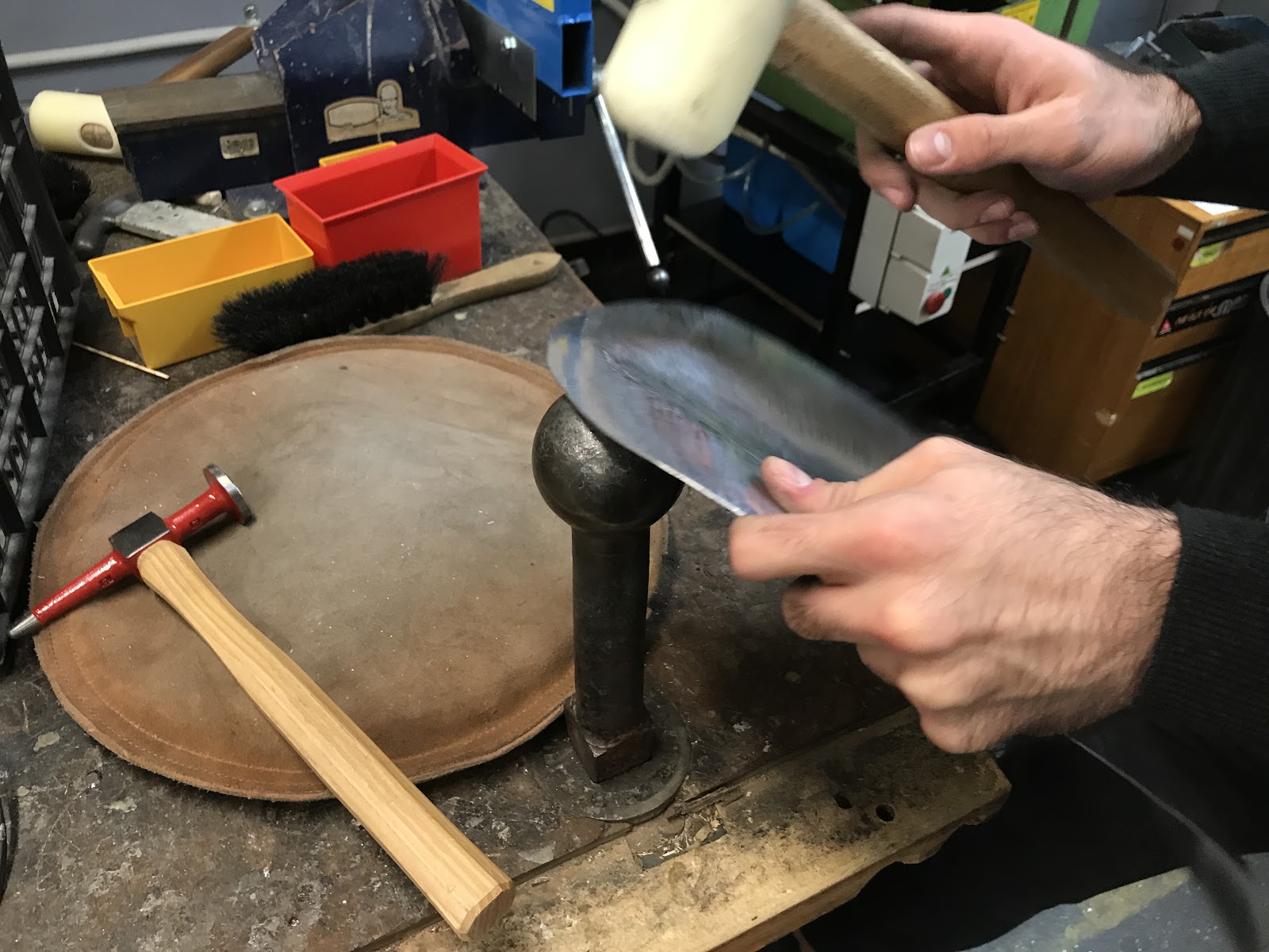
Using nylon mallet to rework panel (2nd attempt)

My first initial working and attempt to produce the side piece, I used a range of dollies and a torus stump to produce a similar shape to the Torus in Assignment 1. This method did not work out as the dollies available weren't the right curvature and produced various dents when starting the piece. This made it difficult to smooth out and pucker out any defects.


Smooth reverse curve using torus stump


Torus (Assignment 1)

Through this process I realized that the aluminium sheet was very sensitive in forming shapes on  due to the difference in scale from the Torus in Assignment 1. This work done on the piece made the initial sheet very complicated to fix since it was overworked. From this I learnt the exaggeration of the term "Less is more".


Blister produced for attempt 2 side panel similar degree than the blister in Assignment 1
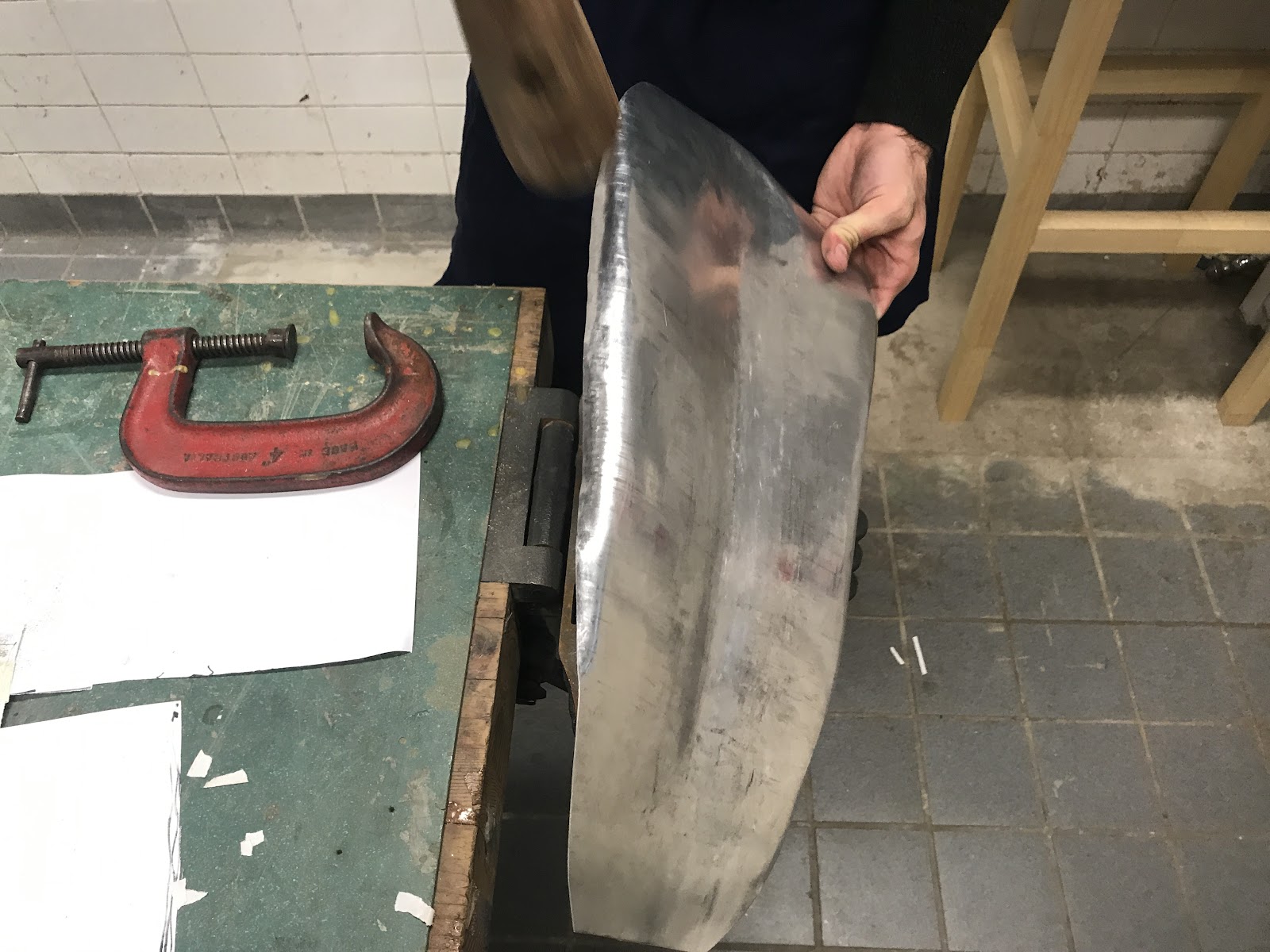
The blister, my strongest and best finished form from Assignment 1
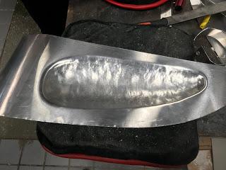
When this process failed, the approached changed to the utility of a blister template to create this indentation for the left side panel. From this i needed to start of with a fresh new piece of aluminum. I chose to take this approach due to it was one of my strongest and best pieces produces from Assignment 1 "The Blister". Above you can see that different between each blister attempt one having a larger scale and one having a more distinct shape according to the template.


Blister outcome before cut o

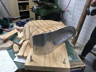
From here I could see how this strength of making the blister once again but at a larger scale and a different shape would be utilized in the world around me such as in bike tanks, chair designs or facade designs. But with this particular strength of making the blister produced a tricky outcome where I was not able to make the panel curve in a reverse direction. I believe this was due to the blister edge playing a major roll in the panels overall stiffness.


Reverse curving stopped by blister

Another weakness in this assignment was that my particular side piece for the fuel tank had to be symmetrically similar to Ryan Johann's right side piece. This forced us to have to work together at the same times and also made us have to always cross reference the form between the template and ourselves.


- Alternatives to Approach:
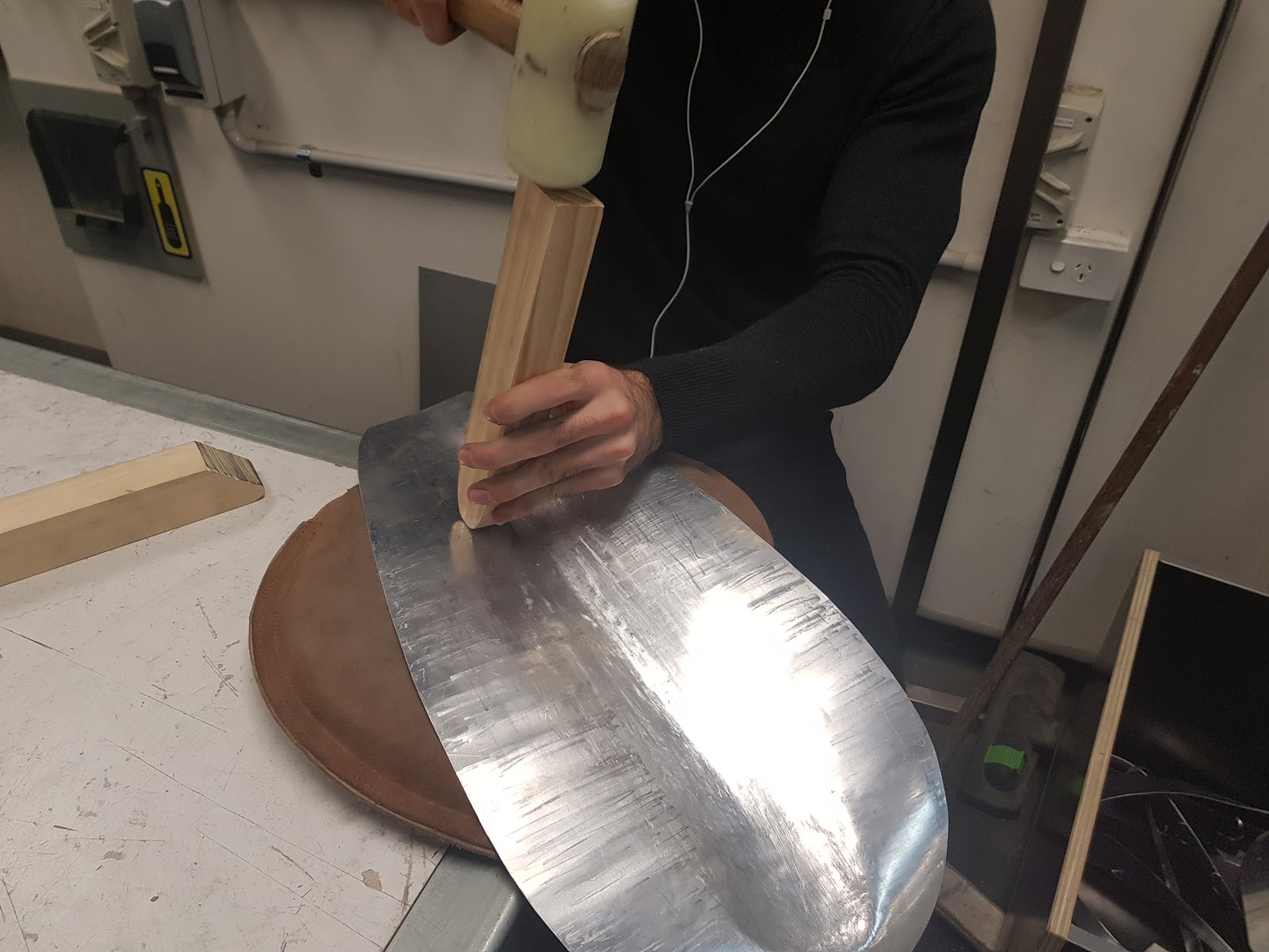
Rubbing method

A major alternative to the side pieces approach was to understand the way the aluminum could be formed in various directions and how would it effect a process or step after a particular form is produced on the side piece aluminium sheet. I tested a method of rubbing the side piece onto the side of a cylindrical stump whilst applying force on each end on the sheet.


Symmetrically referenced to template 

This method had great accuracy results that were referenced with the laser cut template. This method taught me a particular way of how to form a shape that made symmetrical parts to have the same curvature of one another.


Desired curvature of each side panel


As you can see in the images this particular method produced great results and made an alternative approach of receiving a smoother finish than by using mallets and dollies to gain a symmetrical curvature throughout two side pieces.


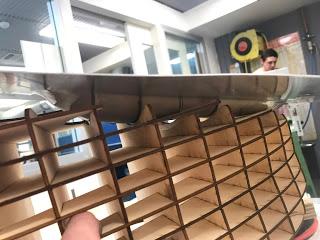
Another alternative approach would be utilizing a blister template but it would have a cross directional curve within the template. This would be to produce an indentation on the side panel whilst maintaining the curvature of the panel in a horizontal direction producing the form needed for the desired shape. Below is a diagram presenting the construction of the alternative approach with particular reference in the aluminium sheets form. The pressure between the two sides of the blister template would need to be fixed together tightly with large nuts and bolts.


Diagram of alternative approach using a blister template


- Alternatives to Techniques and Tools (Demonstration):


The paneling technique was quite tricky to work with as we have multiple surfaces that were inspired by the torus (Assignment 1). The outer edges of the side panels would work with the technique but the interior indentation from the laser cut temple restricted the papers form of being stable and not majorly creased. 


An alternative approach I would use next time is to use the Grasshopper file and extract the side surface and project it flat on a XY plane. The edge of the surface could then be exported into Adobe Illustrator and could be printed and cut out on a sheet with the correct scale. This would of been a more accurate way of extracting the shape of each panel than manually tracing then printing out an outline.


Discovering the power of the small English wheel late in the process was a downside in the forming of the panel. This was great to smooth out any high or low spots as well as producing the exterior curvature needs to sit onto the laser cut template.


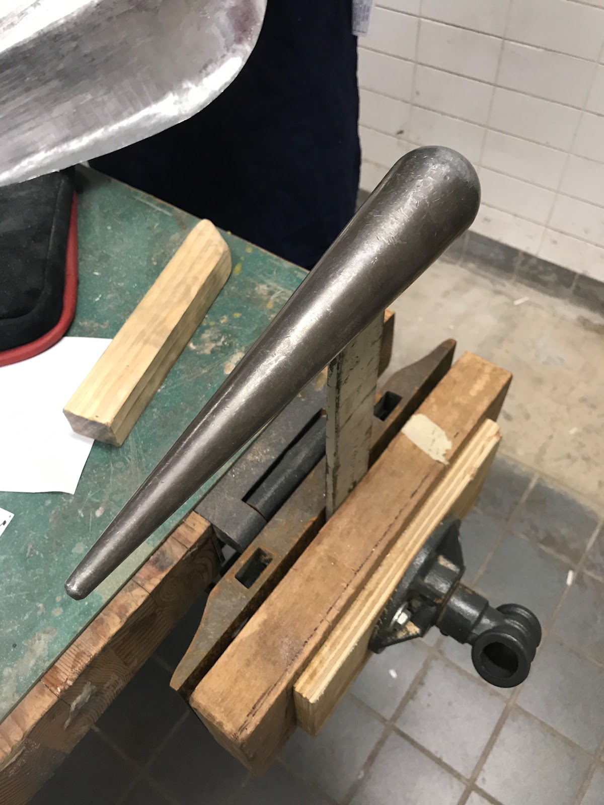
Multiple styles of dollies and mallets were used to force the aluminium piece to have a curved lip around the edges. This produced the desired curve but resulted in marks and compressed the sections of the aluminium. When I started on a new piece I did not used dollies for that particular reason.


Wooden stumps were used to create the torus form and shape, with the sweeping form I had to use various sized stumps for particular sections of panel. This was time consuming in changing for which stump I needed to use but produced great results in the curvature of the panel as desired. One of the largest stumps was close with the degree of curvature needed for the template which was a huge benefit.


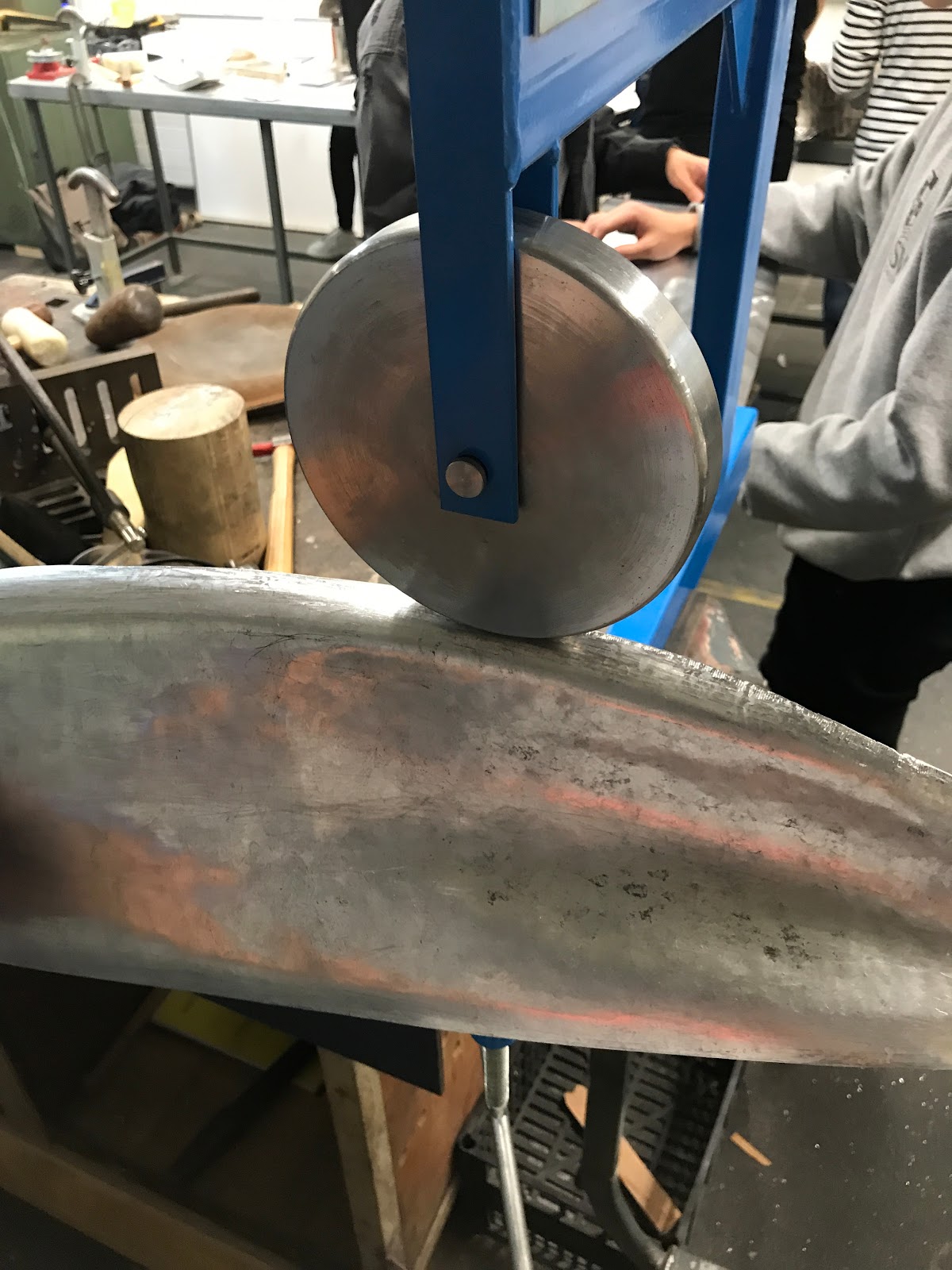
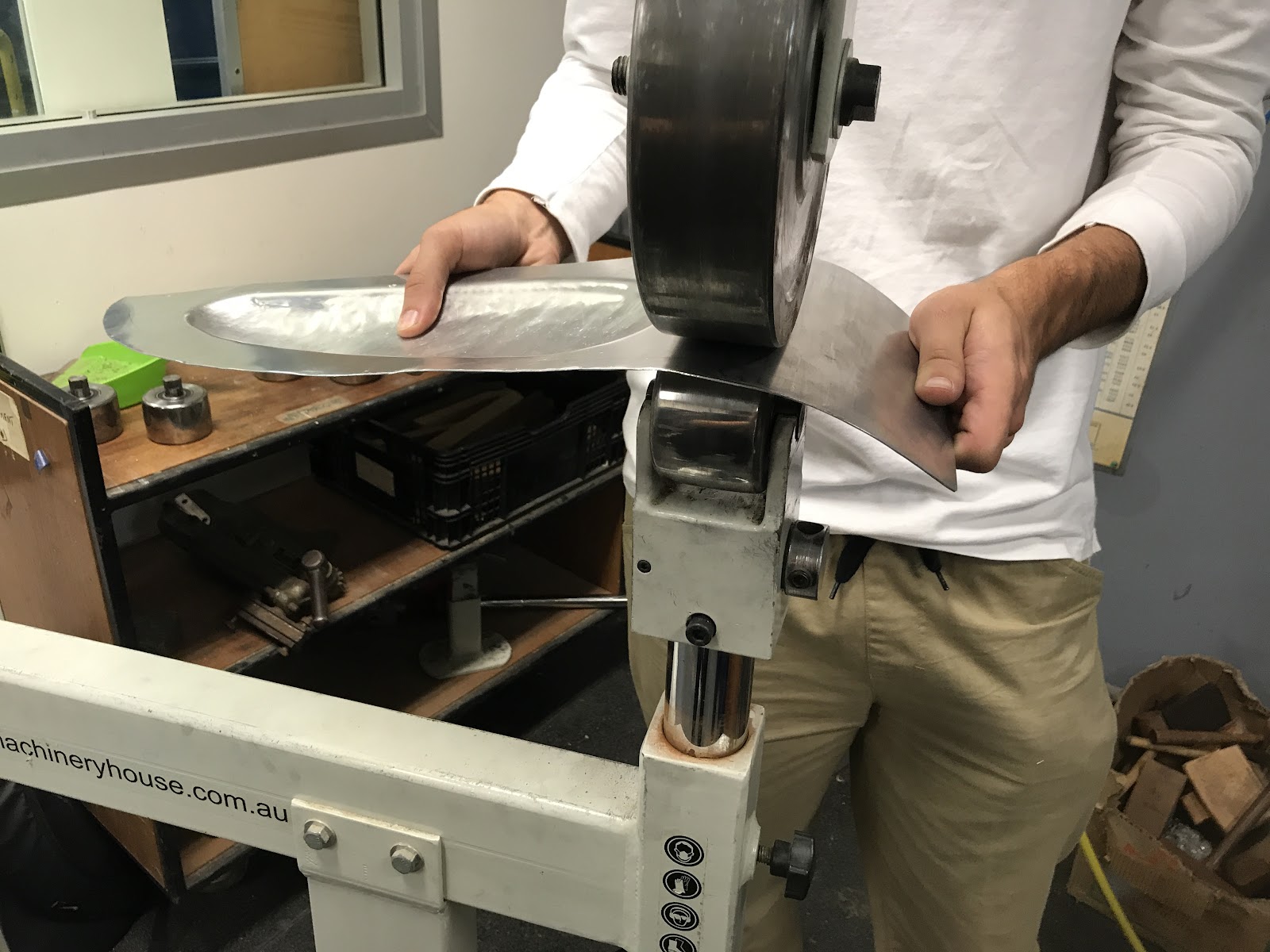
The levered guillotine produced smooth cuts but ultimately warped and distorted the aluminium sheets when cutting due to one side curled up and another when down. This made an uneven panel when cut, I avoided using this tool when cutting with my second attempt at the panel. The large English wheel didn't come particularly handy with attempting my second panel due to the degree of curvature was higher than the most orbital roller for it. This is why for my second attempt I decided to use just the smaller English wheels as there was a wide range of rollers and it could smooth out inside of tight degree curves on the surface (especially the exterior curves).


Contrast and Comparison:


Through contrast and comparison. Comparing and contrasting elements of your work as it developed over the semester with previous examples of your own work or the work of your classmates.

A major aspect of my particular piece of the fuel tank was symmetry and how it related to the overall shape of the assignment. 


With my selected panel of the fuel tank being a side panel this relied heavily on the aspect of symmetry. Ryan Johann created the left side panel. This made the assembly and metal forming process harder than usual. This is because when we worked on forming the panels we would have to work on them the same time and also have to regularly cross reference the panels. This cross referencing involved discussing the degree of curvature to sit on the laser cut template, the methods and tools used to form particular sections of the panels.


Cross Referencing each panel side by side

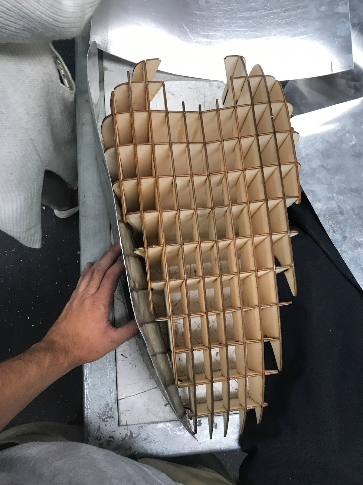
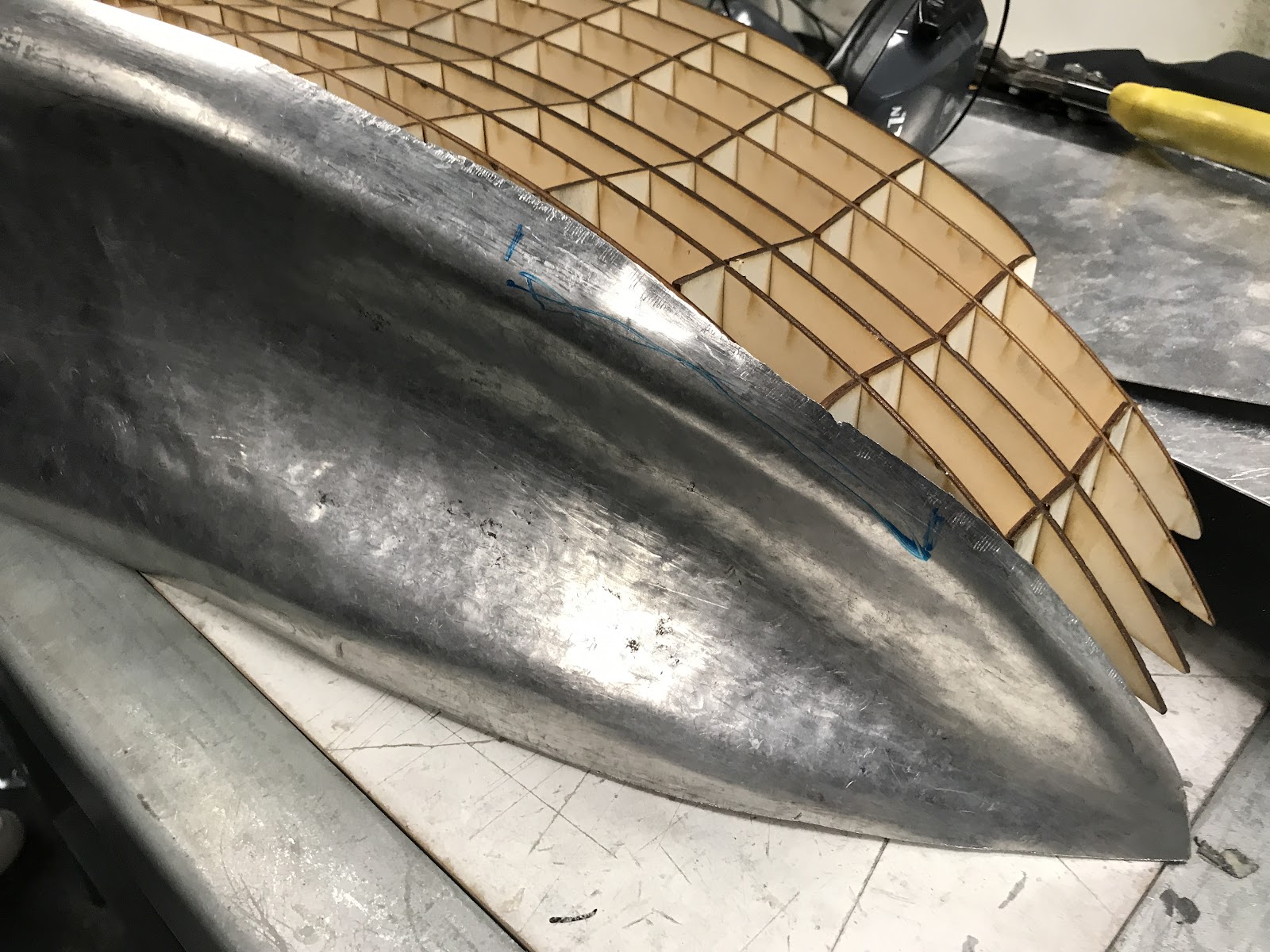
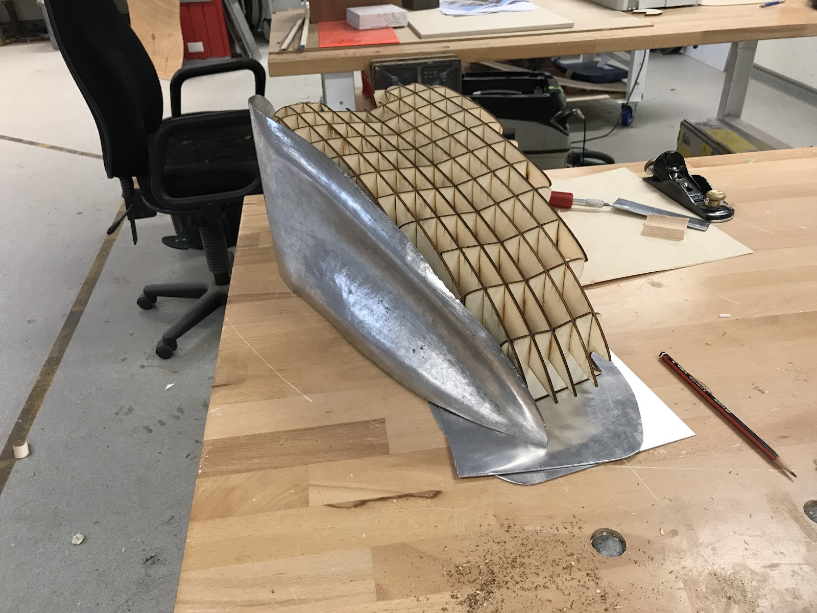
With this comparison method we also discussed which metal forming processes and methods form Assignment 1 that have been proven to give desired results. With using symmetrically driven approach to my panel I had to compare and contrast between the other side panel and the waffle template often to ensure my progress on working the aluminium panel was to standard. 


This angle portrays the optimal comparison and contrasting method of both panel


- Previous examples of my own work:


With the side panels being inspired from the blister and the tours from Assignment 1, I knew that methods from these previous examples determined which processes and tools to use to reach a desired result working with aluminium sheets. This knowledge and skill ultimately carried through into Assignment 2 (Fuel Tank) made the understanding of working towards a from clearer.


The aspects learnt in combining these two separate metal forming objects involved an understanding of relationship between scale, curvature and the shrinking and stretching methods needed for the particular form. The 3 attempts towards the side panel of the fuel tank was frustrating at times but each attempt ultimately progressed myself closer and closer towards the final panel that would match symmetrically with Ryan Johanns' panel as well as the custom made waffle template.


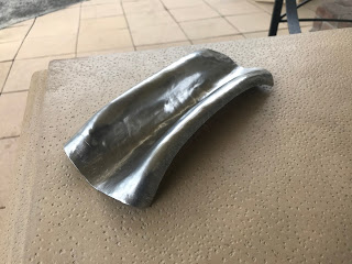
Final attempt of side panel with desired form matching the template


- Work of classmates:


Below is Ryan Johann's left side panel of our custom designed fuel tank. Here you can see how the metal forming processes reference strongly to my right side panel. With the forms portraying a symmetrically driven approach and a well finished piece. Both panels ultimately presents the difficulty of the metal forming process is in industry today. This also presents the combination of utilizing new fabrication processes with traditional fabrication process to form a product.

Ryan Johann's final panel


Reflection on discipline:


The skills of metal forming learnt over the semester has really brought forward concepts that can be carried over into design and fabrication. These would include progressive forming, shrinking and stretching techniques, previous thinking before forming methods, analysis on how a material can react, material properties and limitations. The skills I've learnt have challenged the way I design or fabricate projects in other courses due to the exploration and experimentation of particular processes and methods to produce a same or more accurate outcome. They have also opened up my thought process before and during a design to incorporate and consider possible problems that need to be solved along the way and also has made the common question more outlined, "Is always a better way of doing it?"


Parametric tool (Grasshopper 3d) used to create a custom template that needed to be matched with a manually fabricated produce using traditional techniques (combination of two distinct methods complimenting one another)


Evaluation:


I was surprised and pleased with the result of my panel as I have had no previous experience in metal forming and shaping before starting BEIL0014. The experience has provoked great skills that will be utilized in the future. I can see the groups custom designed 1:1 fuel tank portraying a range of characteristics from earlier assignments such as the torus, blister, tray and bowl. From these characteristics I can see how each methods and form can have implications and applications in industry in relation to shape, form and strength of metal working.


The elements I acknowledge success within are the smooth degree and transition of the gradual implementation of the indentation. This produces an overall aesthetic looking form that personally reflects speed and aerodynamics within the fuel tank. The elements that i would acknowledge to be areas of improvement would include the edge finishes and minor high spots or dents. The edge finishes I believe has the opportunity to be filed more evenly and to be sanded or minorly hammered to decrease the degree of mallet marks. The high spots or dents where produced from the shrinker, I believe I personally should've taken more time and increased the level of accuracy in this process, this would minimize the degree of the high spots or dents.


When i reference my panel with the other panels in relation of how they join and sit proves my achievements and the teams successful collaboration. This uplifts the idea of the power of collaboration. In reflection the tasks from Assignment 1 all carried out various attributes and methods of metal forming that all have a particular purpose behind them. The 1:1 tank has provoked greater knowledge in material properties and working with them to produce desired forms and shapes. The assignment has also proven the complexities and intricacies involved with metal forming in creating custom motorbike tanks.

Tuesday 22 May 2018

Assignment 2: The 1:1 Fuel Tank

Team members:

  • Daniel Camacho z5113840
  • Ryan Johann z5118301
  • Branko Cosic z5060413
The Second assignment for BEIL0014 was to create a 1:1 motorbike fuel tank out of aluminium using the metal forming techniques learnt from assignment 1. In teams we were required to choose one of three tanks to construct; Peanut shape tank found on a Harley 883 Iron or a taller, squarer tank found on the Yamaha IT250 or a custom tank found on a Honda CB550.

My team and I chose to do the custom Honda CB550 tank.

Material:

  • Aluminium sheets
  • 50mm Plywood
  • 4x screw and bolts
  • 3mm birch plywood

Tools used:

  • Nylon mallets 
  • Dolly hammer
  • Sand bags
  • Spanner
  • Custom wooden tools
  • English wheel
  • Wooden stump
  • Guillotine
  • Metal dolly
  • Shrinker 
  • Boben sander

Approach:

Having selected the CB550 tank that was modelled in a modelling program called Grasshopper and having previous experience in the program, we knew we could further push the boundaries of the design to create something more complex than the original design.

Design:

Grasshopper being a parametric based modelling program and using the provided script by Andrew Wallace, we were eager to easily be able to customise the tank to our own design.
However, we were quick to realise the script provided was poorly written in terms of being parametric, this was because the lines referenced from rhino into grasshopper were the main components determining the shape of the tank and whenever you reference items from rhino into grasshopper, you are limiting yourself to the amount of variables that can be changed within a script. This is because lines within rhino are essentially static inputs and not parametrically changeable. We found that whenever we tried to change the lines referenced to change the overall shape the resulting geometry would always break, meaning we could not add any exaggerated changes as we desired. Being extremely limited to the changes we could make, we decided to rewrite parts of the script allowing us to tweak the shape of the tank to how we wanted. This was done by replacing the referenced lines from rhino with grasshopper curve components which were parametrically driven. Thus, allowing us to create our custom tank with exaggerated curves as seen below.


Template build:

With the final design of the tank completed we were ready to laser cut and assemble the template. Within grasshopper we used a previously made script by our team members to waffle and orient the pieces within rhino. These waffled pieces could then be baked into vector lines and exported to Adobe Illustrator. Illustrator is used to set up the laser cutted sheets by setting vector line thickness’ and vectors colours, these two variables are important as they match the laser’s thickness and red is the colour used to know when to ‘cut’, compared to blue for example which tells the laser cutter to engrave. Finally, the sheets were exported to the Trotec laser cutting program ready to be cut. The settings needed within illustrator and the Trotec (laser cutting program) are listed below:

Adobe Illustrator

  • Vector lines thickness = 0.001mm
  • Vector line colour = RGB red 255

Trotec

  • Set material = Birch Plywood 
  • Set material thickness = 3mm (same thickness as the wood use)

With all the pieces cut out, it was then just a matter of putting the pieces together, this can be done two ways, by either referencing the pieces with your 3d model and doing it by eye or by putting them together in order by the engraved labels that reference the orientation and order of build. We used a combination for both.

Dividing panels and metal forming techniques:

The first step was to divide the tank into three sections amongst us. It was obvious that there would be one top panel which would be done by Branko and two side panels were done by Daniel and I. The reason it was obvious is that dividing them by these sections they would require the least amount of severe changes curvatures. Using the knowledge gained from assignment 1 we then began to apply that to figure out our metal forming process.

Top Panel - The top panel was inspired by a torus with reverse curve
Side Panels - The two side panels were inspired by the blister

Blister

After ex tenuous thought of applying a teardrop indentation on the side panels, were came across with the idea of using a blister to provide a shape to fit well on the template. From Assignment 1 we figured that blister was not too time consuming and easy to smooth out with the right type of tools and equipment.

Below is the process of creating the blister template from 50 mm plywood. We used a jigsaw to produce a correctly proportions outline of that blister indentation we desired that would follow the contours of the waffle template. After the outline was produced on two pieces of plywood we used the bobbin sander to create a smoother outline for the desired shape.


Next we utilized a handheld router to create a smoother edge. This was because we wanted an smooth edge of the blister that lead to the flat sheet metal around it. Then we put together the template using bolts as a tightening system.


We started to create a smooth flowing blister using a wide radius nylon mallet, whilst also hitting gentry for gradual stretching of the sheet in the blister template. Later we moved towards using custom wooden tools that where used for particular jobs such as smoothing edge curves of the blister as well as reaching to tight area of the blister template where nylon mallets couldn't.


There was many moments of deconstructing the template to see what curvature was produced as we as following the templates side contours.


With the blister reaching a desired indentation for the side panel we touched up any inconsistencies in the curvature of the blister and smoothed out high and low spots with dollys and utilizing the small English wheel.


Once trimming the side panel from the blister aluminium sheet from the paper template we compared and touched up the curvature of the front part of the side piece using the English wheel and a stump.


Final step of providing the reverse curve on the blister was to smooth the edges out of the blister to make the edge let stiff and more malleable for a reverse curve. We discovery that the reverse curve of the side sheets where difficult to create utilizing various methods of curving the aluminum. Manually forming the curve was too difficult was it produced various dents due to the stiffness of the blister.

Outcomes of Blister:

We tried forming the reverse curve using the English wheel and dollies. This did not play out as the English wheel formed out the degree of the indentation we desire to suit and also the with the dollies the sheet needed to be anchored but this produced huge dents and buckles in the surface. At this moment we needed to re-evaluate an easier method of producing the side indentations with a reverse curve.

Top surface (Branko):

The upper surface consisted of a number of complex curvatures. Individually, they are easily replicated. Although, when applied to one sheet of aluminium like we see here, they act upon each other to make any subsequent changes difficult, globally affecting all other elements in the sheet.
The sheet of aluminium had to follow the sloping contour of the tank, while also maintaining a ‘V’ like taper from its centre, to its edges. This was particularly difficult when considering that it is a very slight taper that was easily disrupted my shaping elsewhere. Furthermore, the receding width from the top of the tank (aluminium sheet) to the bottom along its contour contributed to the V taper difficulty. It then slightly folded over to join to the remaining panels.
The sheet was first shaped using a stump with a curved centred cut out, this allowed for the centre line of the sheet to be shaped deeper than its edges; forming the crude shape of the V, seen below. During this process the sheet was also being shaped along the circumference of the stump in order to follow the profile of the tank. This was done excessively so that any flattening at later stages was accommodated for.


Following this, the impacts were smoothened using the english wheel, taking special care not to flatten the centre line of the sheet, keeping the deepest point of the V taper. Also using the english wheel perpendicular to the sheets centerline in order to help the profile curve while maintaining smoothness. 

The difficulty being that every time the impacts were smoothed, it flattened the top of the tank away from the tapering profile. The curvature that followed the side profile of the tank needed to be exaggerated, so that when it was smoothed and flattened, it would return to resemble the profile curve of the tank (profile outline in blue below).

Given that the centerline indentation does not continue to the edge of the sheet where it would meet the handlebars/frame, it flowed into a circular concave. This portion of the sheet was shaped using a spherical metal dolly, the center line faded into the concave which subsequently neighboured the front edge of the sheet. The curvature on the front edge and sides made this are of the sheet quite stiff and hard to shape, outlined in blue below.

While shaping using the dolly, impacts needed to be relatively light in order to avoid an overpowering spherical shape in this area. Moving the sphere along the edge, while avoiding the center line helped achieve this shape.

The use of the stump and english wheel served to predominantly curve the metal while this surface needed a flatter transition from centreline to edge. In consideration of the provifle curvature, a custom wooden tool was used to help flatten the undulation from centre to edge on either side, seen below. A tool is used because the english wheel flattens the sheet excessively, this way impacts using a tool with a flat contact surface proved more useful. A sandbag underneath the metal helps displace some of the force and better shape the sheet.


When using the custom tool, it is important to symmetrically impact the metal, replicating the process on both sides, this avoided the loss of symmetry. Beginning at the widest point of the sheet, working down to the thinnest. Again, it is important to avoid the centre line, as it is the origin point of the V taper, flattening it would be counterproductive. 

The sheet slowly formed into its shape, checking with the original mold, it fit well, although in order to gain a better joining edge the sheet edges needed to foldover to meet the side panels. Using a combination of the dolly’s below, the edges were gradually folded over. Similarly, beginning from the widest point.


During this stage, it was important to keep referencing the original mold, as well as the side panels. This way the edges would meet with greater accuracy to the remaining pieces of the tank.
The tapered dolly was used at the wider parts of the sheet although not excessively as it would also flatten the overall profile curvature. The curved dolly was predominantly used, while the tapered dolly accommodated it in areas that had less acute edge folds. It also became apparent that the excess material we allowed ourselves during the template stage came in use. The extra material helped ease the process of folding. Although in some areas it was obtrusive. In this case, the metal was cut away slightly using snips or a sheet cutter. This sometimes deformed the pre-existing shape at the cutting location but it was not aggressive enough to deform the sheet globally. Gradually through the process of shaping, a cyclic process emerged where overworking the material would cause it to flatten. This caused a return to the stump hammering and subsequent smoothening, followed by the more intricate edge folding and concave processes. The most effective way to achieve the end was restraining from any excess all of these shaping processes. An excess in any one tool/process would negatively affect the rest of the sheet. It was important for each process to mediate the next, predicting the reaction of the metal to a given tool or action. This mediating did extend the shaping process significantly, but it was necessary in order to maintain symmetry and achieve the final form, viewable below. This form was then polished and mounted along with the side panels on the mold. 

Side Panels (Ryan & Daniel):

After finding out the blister was not the best method we had to re-cut new side panels and decided to approach it with the same technique as the top panel, by using a torus with a reverse curve. The idea behind using this technique is that it will allow us to make the side panels malleable to achieve a reverse curve with an indentation on each side that is symmetrical.

First method included with having an extra 1.5mm around the whole side panels for achieving some tolerance when joining the 3 pieces. This extra material would allow for tolerance with shrinking and stretching the side pieces in particular areas.

After we started to look back at the processes that worked successful doing Assignment 1 “the Torus”. This incorporate the methods using a round wooden stump with a recess on the side. This recess provokes the sweep whilst on the flatter parts produces a reversing curve. This method needs to be carried out with care as bucking and denting prevails across the inner sweep.


The utility of various sizes of nylon and wooden mallets started of that producing the inner sweep gradually starting from a very wide mallet to a very narrow mallet that could stretch the inner sweep to the desired degree. Various changes where made in the sizes of the wooden stumps this is because the waffle template changes direction and size of the inner sweep. So a larger and a low degreed sweep stump was be suitable to start from the start of where the indentation starts on the side panel. A smaller stump was needed for a tighter and high degreed sweep.


This method incorporated two variables of curling the overall side panels in one direction with also producing an indentation that gradually came into the front end of the piece and ended as a exaggerated effect towards the end. We figured that doing this method slowly with care produced grater results than just forcing the piece to adjust to the stumps overall shape. This ended up saving critical time in producing the form of the side panels and produced easier finishing methods that were to come.


Once we got the desired fitment, degree and curvature of side panels against the waffle template we utilised the smaller english wheels to smoothen out any high or low spots. We utilized the smaller english wheel due the degree of curvature of the side panel wouldn’t sustain shape on the larger english wheel due to the width and degree of the wheels.

The small english wheel also was utilised to exaggerate a bird wingspan shape or sweep. By applying horizontal pressure to the side panels whilst in the english wheel made the overall shape further exaggerated. This benefit was more time efficient and had more even finishing than using a dolly whilst also smoothing out any minor high or low spots across the panel.


Once we were pleased with the degree, smoothness and curvature of the side panels that followed the waffle template, we decided to concentrate on the front end of the side panels and figure out practical methods of producing a evenly curved from piece. With the pleased experience from Assignment 1 “the Bowl” we decided to use a similar method of using the english wheel but producing a change of degree or “flick” with every finishing roll on the larger english wheel. This produce the degree of curvature we wanted whilst keeping the form of the indentation across the piece. This was a risky method due to a high possibility of denting the start of the reverse curve and sweep of the indentation. But in the end it payed off due to the care taken and applying intervals of light force to the sheet.


After this process we had to start looking into the joining process of the top piece in relation the the side panels. With reference to all panels we decided to exaggerate the outer curves of the reverse curve so it could meet underlap the top piece with the same angle and have similar degree in meeting areas. This was done using various types and shapes of dollies. This relied heavily on symmetry and alignment of the panels.


Joining Ideas:

Throughout the process of making the panels we kept into consideration that we would potentially have to join the pieces together. We did this by leaving 2cm of extra material along the edge of all the panels when we initially cut it, this would allow us to use this extra material to fold over each other which could then be able to be welded together or simply pop riveted.

However, we soon found out it was not required to join the panels together for submission so we then decided to use this extra material to carefully trim and fold a neat overlap between the joining sections.

Group Reflection:

We are surprised and pleased with the result as we have had no previous experience in metal forming and shaping before starting BEIL0014. There was good communication within the group where all pulled their weight and tackled their responsibilities well. Our final opinion on the shape we customised is that we are please with the scale and details of the bike tank. We also have minor adjustments or recommendations individually about the degree of the form and shape. The experience has provoked great skills that will be utilised in the future. We can see our custom designed 1:1 fuel tank portraying a range of characteristics from earlier assignments such as the torus, blister, tray and bowl. From these characteristics we can see how each methods and form can have implications and applications in industry in relation to shape, form and strength of metal working.

Final Results:

Final Pictures:

Personal Reflection - Daniel:

Through my individual piece of the tank i am quite pleased and surprised from the result I produced with no metal forming or shaping experience prior to starting BEIL0014. The elements I acknowledge success within are the smooth degree and transition of the gradual implementation of the indentation. This produces an overall aesthetic looking form that personally reflects speed and aerodynamics within the fuel tank. The elements that i would acknowledge to be areas of improvement would include the edge finishes and minor high spots or dents. The edge finishes I believe has the opportunity to be filed more evenly and to be sanded or minorly hammered to decrease the degree of mallet marks. The high spots or dents where produced from the shrinker, I believe I personally should've taken more time and increased the level of accuracy in this process, this would minimise the degree of the high spots or dents.


When i reference my panel with the other panels in relation of how they join and sit proves my achievements and the teams successful collaboration. This uplifts the idea of the power of collaboration. In reflection the tasks from Assignment 1 all carried out various attributes and methods of metal forming that all have a particular purpose behind them. The 1:1 tank has provoked greater knowledge in material properties and working with them to produce desired forms and shapes. The assignment has also proven the complexities and intricacies involved with metal forming in creating custom motorbike tanks.